MILESTONE PROJECT 1: STACKED SLICES MODEL
I was assigned to build a stacked slice model using grasshopper and laser printing.
Research
I looked for some examples of this project and found some interesting examples.


I think these examples are interesting since unlike other examples the instructor showed, these structures have slices arrayed on circular shape and it is showcasing much free-er form than just shape extruded from the bottom and laid on the bottom. And some of the examples were showcasing very organic form and I think organic form made with high technology like laser cut is such an interesting irony and wanted to try it.
Planning
While doing previous projects, I saw some YouTube tutorials explaining how to build a wavy wall. I thought maybe I can build a wall that is looking similar and use slice command in grasshopper.

Modeling
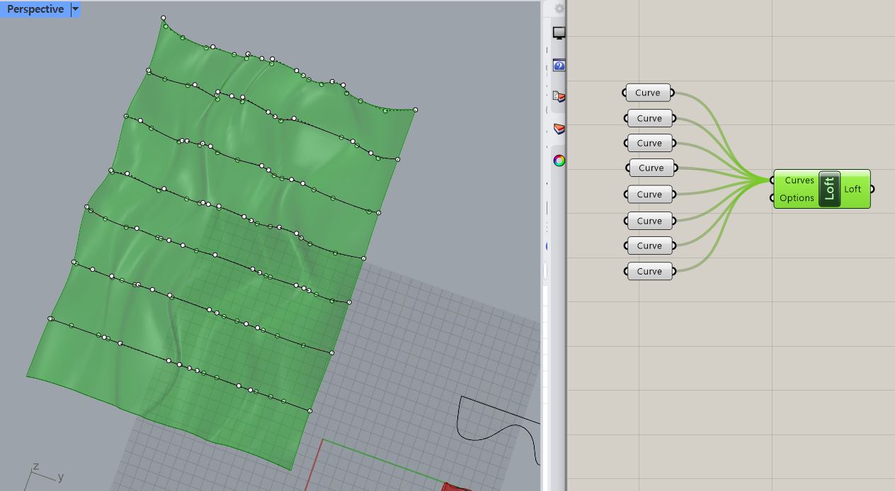

At the first time, I made some organic curves, assigned to "curves" in grasshopper and used "loft". However in the next week, we learned how to build irregular wavy wall. So, I decided to practice with it. The way I studied this is shadow boxing the definition of the map that the instructor shared, from the scratch.
From the construction point, drew lines using 'Line SDL' and attached a number scale to length port (adjusting depth size of the final structure).
Using 'Move' the lines were copied multiple times and arrayed along x lines with certain gaps among them. the number of copies and gaps among them are adjusted with setting up 'construct domain' with number scales, which are attached to multiplication-range-Unit X to adjust the width size of the structure.


After that, 2 sets of the dividing points were shown on the lines by using 'divide curve' and 'move', 3rd sets of dividing points are built by using 'construct point' and displayed on top of second set. The height among them( 1st set and the 2nd set) can be adjusted by using number scale through 'Unit Z' attached to 'move' which is connected from highlighted 'divide curve' points shown in the image below. When the 3rd set of points were built, it took the information of the 2nd set made with 'move.' The information is 'deconstruct' into X,Y and Z value of each points and while the 3rd set of points used X and Y value of it, there were some additional value was added on Z value, to build the wavy from on top of the structure by giving random additional numbers on top of its original value came from 'deconstruct'.


The number of Z values that are gained from 'deconstruct' is counted with 'list length' and connected to number port of 'random,' this means that as results, random will make that many values. For random's range, 'construct domain' is built and connected to it. The number of seeds changes depending on how many numbers of original line stems from the starting point, and it is currently same as the number of lines (10). And that seed is grafted. This means that, the 3rd set of points (made after 'deconstruct' and 'construct point') that are stem from each lines made were all in the same bag before(line 0's bag with 10 points on it, line 1's bag with 10 points on it...=140 points in 10 bags, 14 points each in one bag ) but by grafting each individual points are now in a bag just by itself (line 0's 1st point, line 0's 2nd point...line 9's 14th point=140 points in 140 bags). And this will expand the number of values random would have given to us into 14 times, giving all those random value to each individual points made from 'move' and by added on its Z value, eventually giving random heights on points made from 'deconstruct'-'construct points.' In the image, the range for random was set for only 1 number since port B of multiply was not changed and stayed as default number (1), so it all had same changes.

I also found that the dividing points are not spread to Y direction. The problem was that when I was starting lines to divide, I didn't set the direction port of 'line sdl' and as default, it displayed lines on Z direction. So, I set the direction to Y again.


After building 3rd level points, 'interpolate' came to make curves that are connecting all the points on each line. That is connected to 'end point' to figure out each curves' start and end points. 'End point' is connected from original line as well.


Lines connecting 'interpolate' line and original straight lines were made, using 'end points' and all of those curves were joined, with 'join curves.'

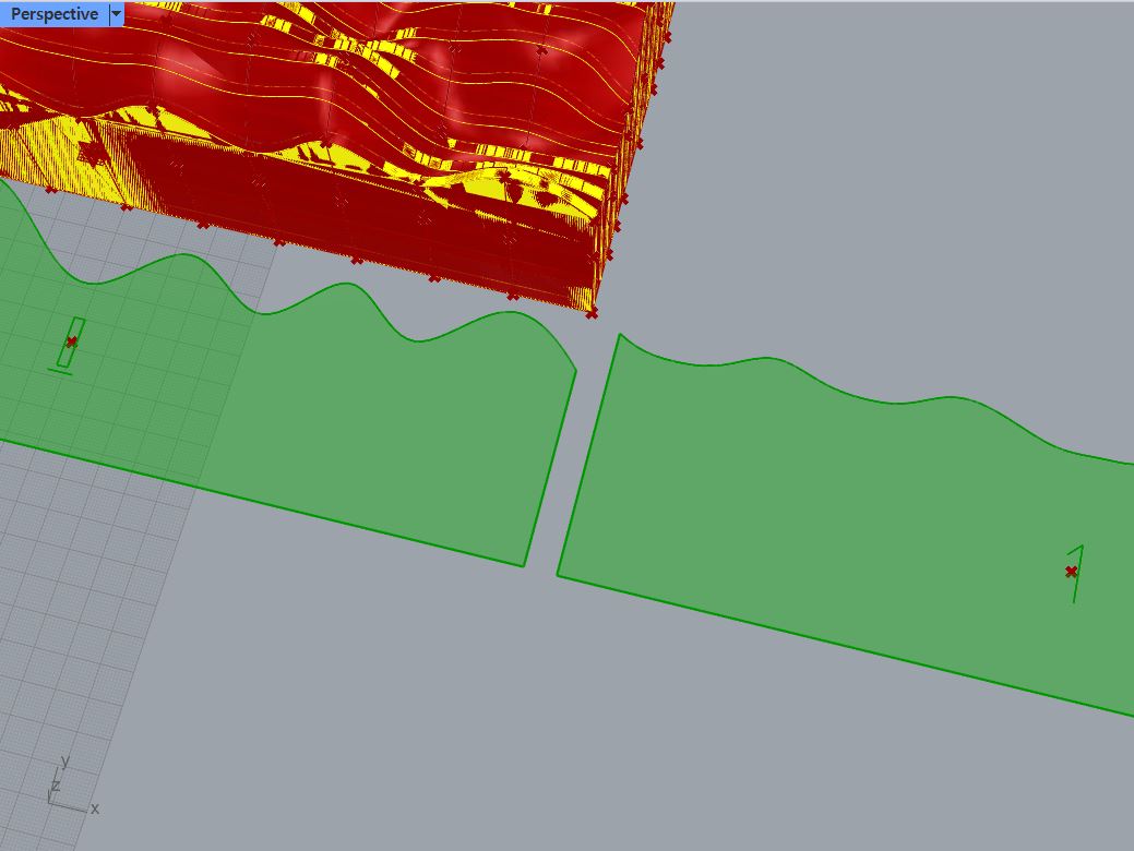
That close curves are connected to 'Loft' and made a brep, that brep is closed with 'Cap Holes,' making 6 sided brep with one of the sides having wavy surface.


Now that I made a brep to cut, next step will be slicing it. To get the cut lines of pieces, I used 'Contour' to make contour lines (=future cut line), and as a default, it showed horizontal contour lines like this image right below.

That is when 'Stream Filter' came in. What it does is that by selecting the gate from the top port, it can let us to chose which one port (from the pictures below, it is shown as 0,1 and 2. In a close look, black dots have plus sign is shown between those numbers and it lets us to have more or less options) below we will use among.


Using stream filter connected from Unit X,Y and Z, after that connected to direction port of 'Contour' now I can chose which direction I want to cut my brep. To control the thickness and numbers of pieces we will get from this brep, a number slice is added and connected to Unit factors and it connected to 'Addition' with another number slide connected to B port of 'Addition.' This value is connected to distance port of 'Contour,' and by doing this we can see there are gaps (B value of addition) were added among pieces. Now that I think, maybe without this gap my structure could have had more natural connection between pieces.


After contour lines are made, it is connected to 'Boundary Surface,' which connected to 'Area.'
('Rotate Direction.' The planars made with 'Boundary Surface' was arrayed along Y axis as we set at 'Stream Filter' stage, and now it is arrayed along Unit Z thanks to 'Rotate Direction.' doesn't seem to be needed for this though.)
Planar surfaces are laid in a row by using 'Pack Objects.' Plane to be laid on was selected by 'Stream Filter' connected through 'Area's centeroid. After all the pieces were laid, in their centeroid, the text were used to label each pieces. It is displaying numbers collected by using 'List Length'-'Construct Domain'-'Range'-'Round.' Planars' edges info was collected by 'Brep Edge' and these are the cut line that I will use for laser cutting.


The planars were extruded by using 'Extrude.' This will be used to finishing my design.


Designing
- 24 Pieces Version -


- 36 Pieces Version (Discarded due to budget) -

- Angle Variation -


- Depth and Gaps between Pieces Adjustment -


Final Look


Laser Cut Preparation

< Pieces for gap study-to figure out how big gap is needed to fix pieces >

< Final Cut File, with gaps of 2.68 mm. Actual thickness of the material was 2.88 mm and from the gap study, I learned that the laser made the gap bigger by 0.1 mm on every edges when printed it. >
Laser Cut


Assemble


Final Presentation


It was a project uses random value to get organic structure. By using grasshopper, when I had to adjust my design I could easily edit it by using number slides built in the definition. For this design, since I was following definition that was already built I used the design involving gap, however I think I will try to edit it in different ways, trying different slicing directions and angles. By the way, using black opaque acrylic board as a material was not really successful. It looked very industrial because of the feel that the material deliver. I wish I can find tinted transparent black acrylic board to build this again. Or using wood board will reduce industrial feel.


댓글
댓글 쓰기